jeudi 26 avril 2018
jeudi 8 mars 2018
DIY Plywood CNC Router construction timelaps video
In this video you can find some details about the fabrication process that we went through. Here you go, a DIY Plywood CNC Router construction timelaps video
We were heavily inspired by book of Patrik Hood Daniel titled "Build your CNC"
The electronics :
- Arduino nano with GRBL installed G-code interperting
- 3 Toshiba TB6560 stepper drivers
Modification d'un routeur de la marque Telefonica, ajout d'un port USB
J'ai acheté récement un routeur en
bonne occasion de la marque COMTREND CT-5653 issu de l'opérateur telefonica
(voir image en bas).
Alors en googlant un peu sur ce
modèle j'ai découvert qu'il peu être flashé facilement et rapidement avec la
magnifique distribution linux embarquée : OPENWRT. Et en plus de ça, On
peut y ajouter un port USB Host. C'est-à-dire, un port qui peu recevoir
d'autres périphériques USB clients comme ceux utilisés pour l'acquisition de
données par exemple : une souris USB, une Webcam, voir un scanner ou une
imprimante.
Pour pouvoir ajouter ce port hôte à
notre routeur, on a besoin de quelques composants électroniques facilement
trouvables, qu'on peut acheter chez les revendeurs en détails des composants
électroniques, ou bien qu'on peut récupérer facilement si on dispose d'un stock
de cartes électroniques non utilisables mais non ancienne (car ces composants
doivent être en forme CMS – Composants Montés en Surface).
Donc, en bref, il faut réaliser deux
modifications à ce routeur, une sur le hardware, et l'autre sur le software.
Comançant tout d'abord par le
hard :
Il faut s'assurer qu'on dispose du
materiel suivant de toucher quoi que ce soit dans le hard:
- un fer à souder à tête très
pointue.
- De l'étain mince.
- Un régulateur de tension LM7805.
- 3 résistances 15kΩ en forme CMS
7805
- Un condensateur 470µF
- Un condensateur 0,1µF
- Un condensateur 0,33µF
- un peu de fils pour le câblage.
- Un connecteur USB Host Femelle.
Il est à noter qu'il n'est pas
conseillé de faire ces manipulations si vous n'êtes pas habitués à faire ce
genre de travaux de la soudure avec le fer à souder, sinon vous risquez
d'endomager votre routeur.
Procédons comme suit :
Dévisser les deux vis du boitier
externe. Puis détacher la carte électronique, en démontons le connecteur de
l'antenne de la carte Wifi, il est facilement reperable.
Voyant l'image suivante :

Comme on peut le voir, parmi les
zones encadrés par le jaune, il y a une, située au milieu, appelée USB HOST,
c'est là notre espace de travail.
Les traits en rouge représentent des
shunt ou courts circuit que on réalise avec des morceaus de fils.
Les zigzag en vert représentent les
résistances de 15kΩ et l'emplacement où ils doivent être soudées.
Le seul trait qui est en noir,
représente une résistance à valeur nulle qu'on appel un strap ou shunt qui doit
être enlevé ou désoudé.
Et en bleu, le condensateur de
470µF.
Reste la partie d’alimentation. Alors
là, vous avez le choix, soit de réaliser le montage du schéma en bas de l'image
encadré par un rectangle blanc dans une carte à circuit imprimé brute, ou
pastillée. Ou bien essayer de les souder et les laisser en l'air. Moi j'ai
choisi la deuxième,solution. L'entrée du régulateur de tension se branche
directement sur la carte dans l'emplacement 20V écrit en rouge dans l'image
précédente. Puis en soude la sortie du régulateur aussi dans la broche appelé
dans l'image « ENTRADA PARA 5 VOLTOS »
mardi 6 mars 2018
My Resume
Please download my resume using the link below :
https://drive.google.com/file/d/13Xvui6Acm401uhG64zAYo91DaPjrqmLe/view?usp=sharing
https://drive.google.com/file/d/13Xvui6Acm401uhG64zAYo91DaPjrqmLe/view?usp=sharing
mercredi 13 avril 2016
DIY cheap desktop CNC made from scrap - Z axis Part 2
This is the first test of my homebrew homemade DIY cnc machine with a pencil trying to draw a circle using grbl for G-code transfer inkscape for the drawing and makercam to generate the G-code.
Below some pictures of the machine

 below a picture of Y-axis driven by a belt system

the Z-axis


Below some pictures of the machine

The X-axis is driven by a threaded rod system


dimanche 20 septembre 2015
A Data acquisition card for fault diagnosis of DC Motors - Part 2
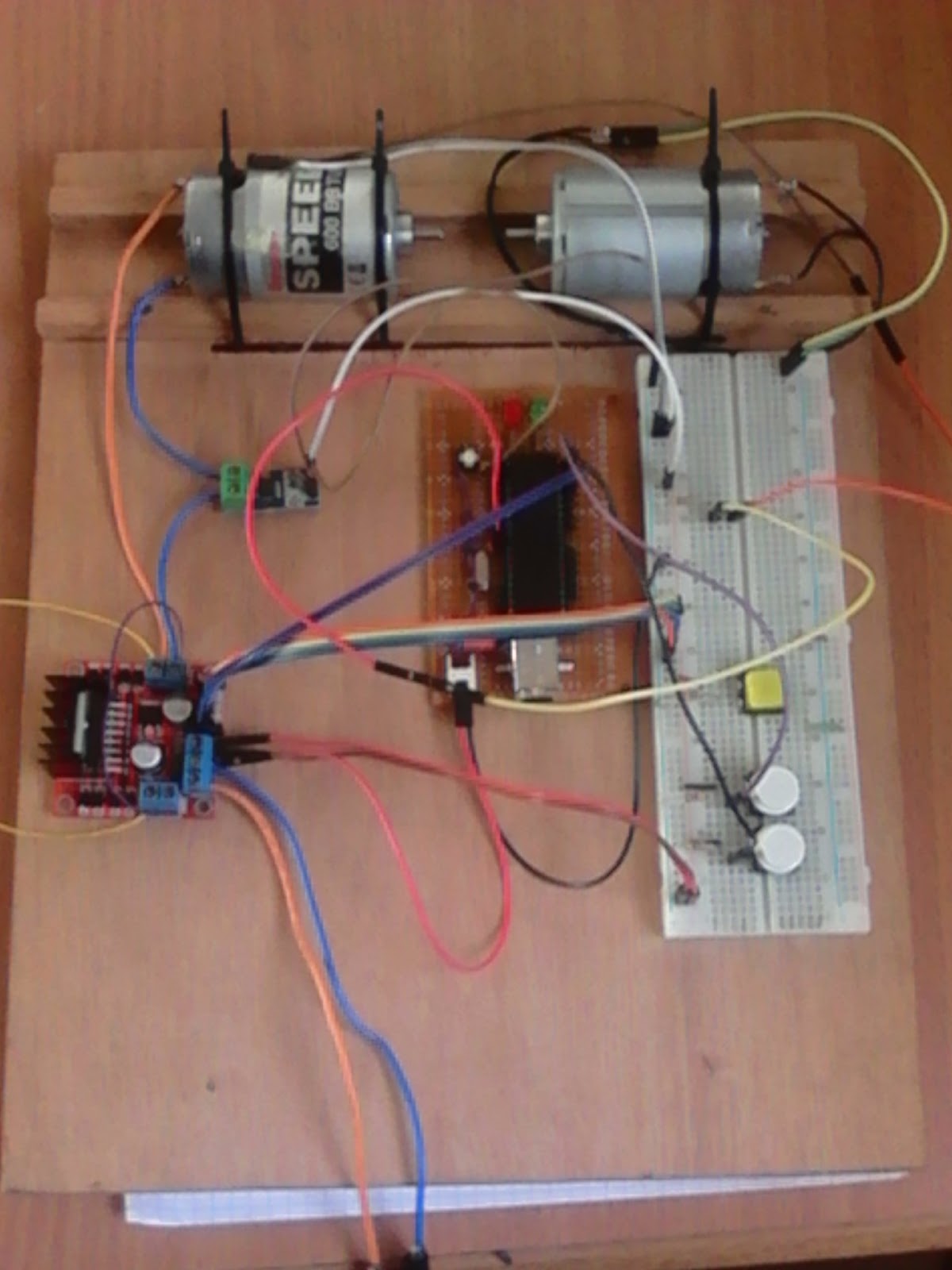
Here's an up date of my data acquisition system work bench that i presented in a previous article. I decided to share some of the additions that i made to the system.
In the next picture, one can see some of the added elements comparing to what was presented in the previous article.
 |
| A new version of the data acquisition system |
In this picture, one can notice downside the the workbench another added system. This a permanent addition, but used temporarily to measure RPM ( rotations per minute ) of the motor's shaft in order to calibrate two belt-in tachometers inside the system.
 |
| A new version of the data acquisition system with external tachometer |
Here, you can see some of the used sensors witch is the DS18B20 digital temperature sensor. In that spot, it measures the external temperature.
 |
| A DS18B20 digital temperature sensor |
 | |
|
In the picture above, one can see one of the RPM sensing methods witch is an optical sensor to detect the instantaneous passage of the shaft.
 |
| Zoom in into the RPM optical sensor |
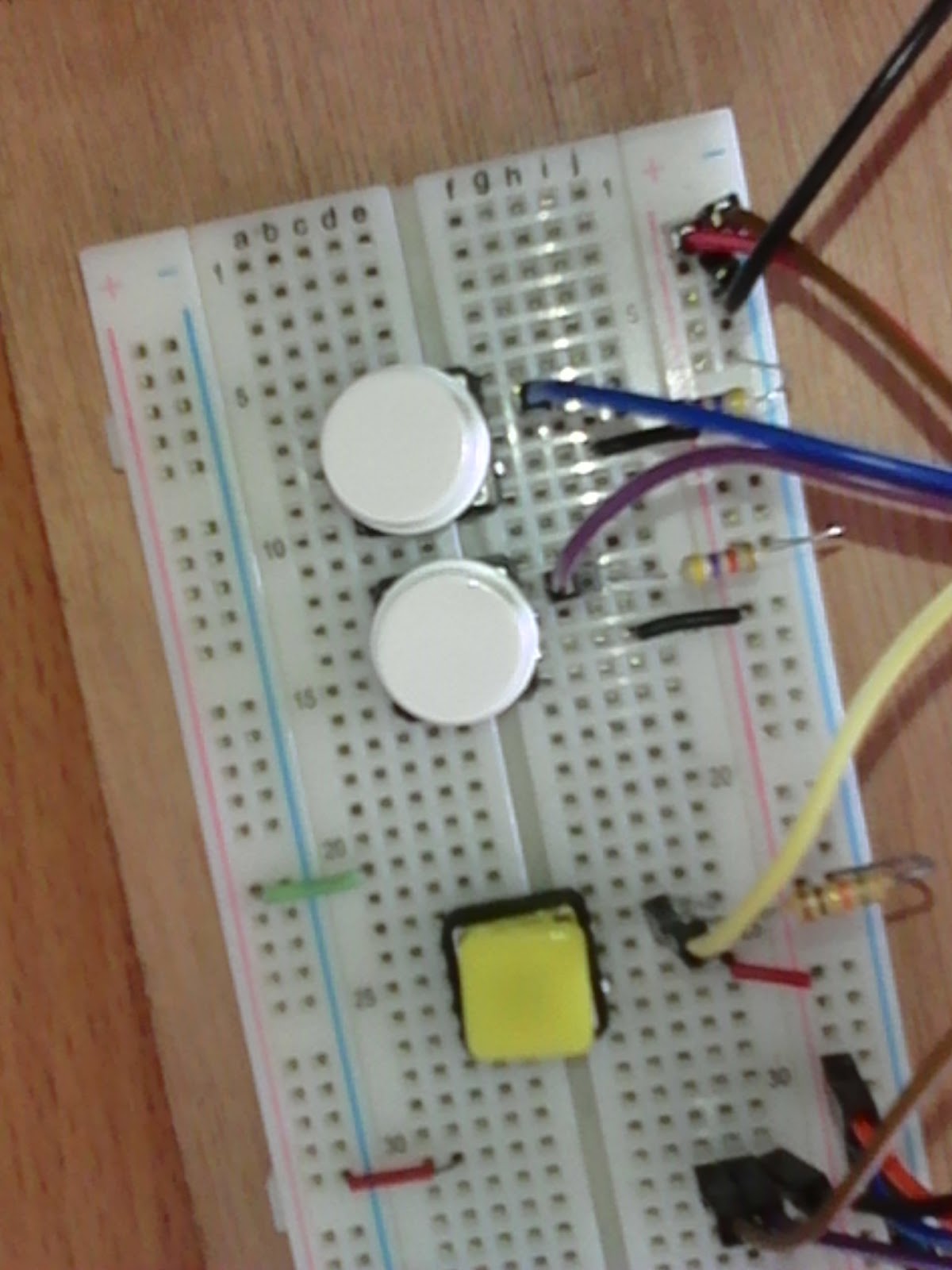
Now, it is done by a simple 10k ohms trimmer. The Yellow button is still there.


mercredi 9 septembre 2015
A Data acquisition card for fault diagnosis of DC Motors
A Data acquisition card for fault diagnosis of DC Motors part 2
I designed this project for the sake of research. In the fact, i needed a system that generates massive reel data for learning some artificial intelligence/machine learning models such as Bayesian Networks or Bayesian Belief Networks or simply probabilistic graphical models.
After several designs, firstly by using Microchip PIC microcontrolers in the hart of the system, then by merging to AVR, to finally ending by using Arduino. I succeeded finally to have a platform to generate the required Data that i need in my field of research.
The goal after all for this project is to design a system that perform a fault diagnosis of DC Motors in special case and for industrial machines in general. In other term, it's a an experimental bench for the proof of concept of machine learning theories.
These are some pictures of the project in prototyping phase.
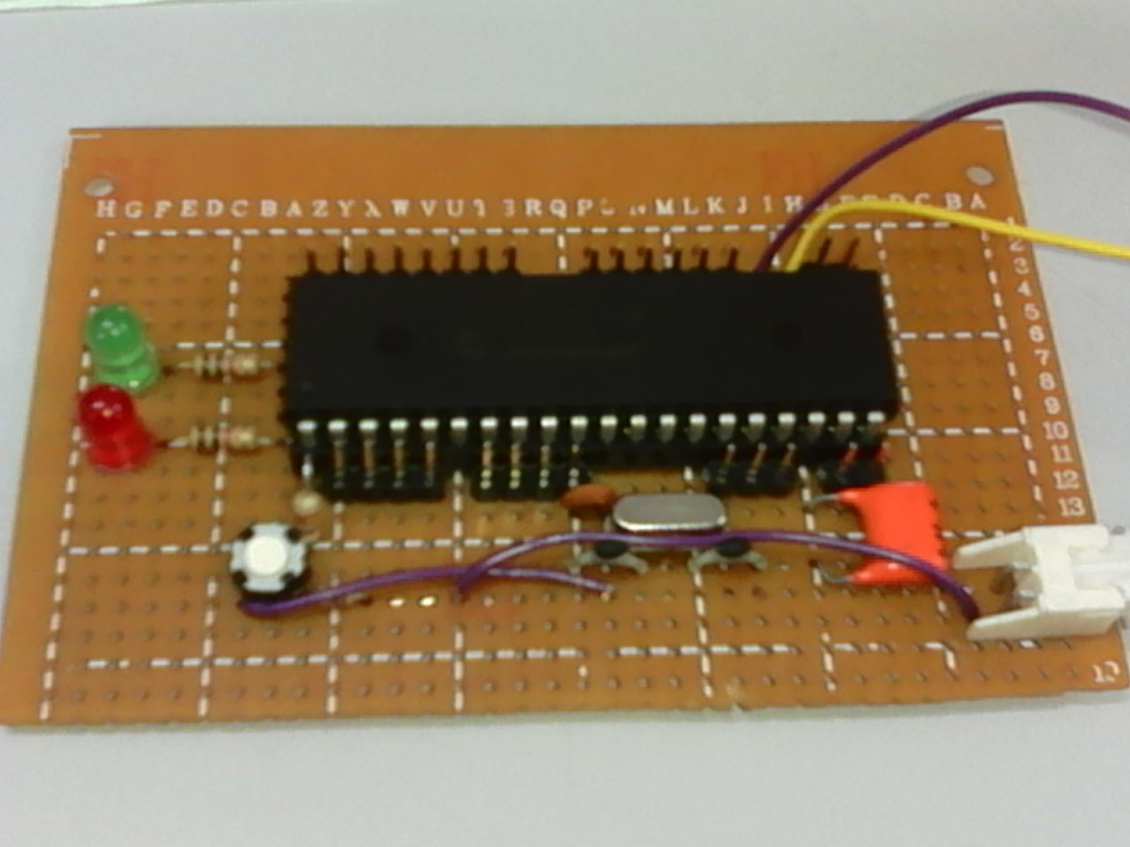 |
| Pinguino card based on PIC18F4550 that i made and used in earlier versions of the project. |


 |
| L293N based Dual H-bridge stepper/DC motor driving card |
 |
| Some version of the project after merging to Arduino |
 |
| A Raspberry Pi B+ microcomputer that i plan to use to replace a normal personal computer for learning the Bayesian networks that i need |
--> CIMSI'14 international conference Paper
--> IJCA International Journal Paper
Inscription à :
Articles (Atom)